Thank you for purchasing the Raspberry Pi Parallel Hat for LinuxCNC! This setup instruction assumes you are using the 5 axis breakout board that is available everywhere. There shouldn't be any difference between the green and blue breakout boards and either one should work.
Download the LinuxCNC RTOS Image
Please download the latest uSD card image from linuxcnc.org.
https://linuxcnc.org/downloads/
Make sure to download the correct version based on whether you are using a Pi4 or Pi5. For Pi3, use the Pi4 image:

Older versions of the OS image can be located here:
Burn the uSD Card
If you use Linux to burn the image to the uSD card, the Raspberry Pi Imaging application seems to work well:
https://www.raspberrypi.com/software/
If you use Windows, the Raspberry Pi Imaging application can also work, but it crashes on some Windows machines, so an alternative is the Balena Etcher:
Turning Off SPI
The first thing that you will need to do once you boot up the raspberry Pi is to disable the SPI peripheral. By default, the Raspberry Pi image defaults to the SPI port being enabled. The trouble is, LinuxCNC will attempt to use those same pins as GPIO. There is a conflict and the error message will be:
gpiod_line_request_reconfigure_lines: Assertion `request' failed.
You will need to use the terminal to modify the config.txt file located in or near the following locations:
- /boot/firmware/config.txt
- /boot/broadcom/config.txt
Open the file using the nano application once you find the location in the terminal.
sudo nano config.txt
Find and modify the "dtparam=spi=on" line so that it is off. It should look like this:
dtparam=spi=off
"Ctrl-O" to save, and "Ctrl-X" to exit.
Note: you will need to reboot for this setting to take effect!!
Physical Connections

! Please click on the image for a larger version. !
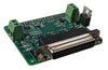
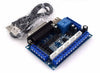
The 5 axis breakout board comes with a male to male USB cable. Throw it away and don't even let it get near the junk drawer of random cables. It should not exist. The 5 axis breakout board will get it's power from the "PC5V" and "GND" terminals on the bottom edge. Higher voltage for the 0-10V analog output is obtained from the "GND" and "+12-24V(IN)" terminals on the right side. The above image shows two separate power supplies, but a single 24V power supply could easily be used for both the breakout board and the stepper motor drivers.
In order to connect the 5 axis breakout board directly to the Parallel Pi Hat, please remove the small standoffs on the parallel pi hat DB25 connector using a pair of needle nose pliers.

If you are using a DB25M-F parallel port cable to connect the Parallel Hat to the Breakout board remotely, leave the standoffs in the Parallel Hat as they will be necessary to secure the cable to the board.
A simpler connection diagram is located here:
https://www.jbcnc.se/images/datasheets/DB25_0-10v.pdf
A general wiring best practices guide is provided by LinuxCNC here:
https://linuxcnc.org/docs/stable/html/integrator/wiring.html
Pinouts
If needed, here is a table of the pinouts. When modifying the HAL file, please be mindful of the difference between the Pi pin numbers (referenced in the HAL) and the DB25 connector pin numbers (which connect to the breakout board).
| Pi Pin | Pi4/Pi5 2023 HAL | Pi5 2025 | DB25 | Breakout Function |
|---|---|---|---|---|
| 21 | hal_gpio.PIN21-out | hal_gpio.GPIO9-out | 2 | XSTEP |
| 19 | hal_gpio.PIN19-out | hal_gpio.GPIO10-out | 3 | XDIR |
| 23 | hal_gpio.PIN23-out | hal_gpio.GPIO11-out | 4 | YSTEP |
| 29 | hal_gpio.PIN29-out | hal_gpio.GPIO5-out | 5 | YDIR |
| 31 | hal_gpio.PIN31-out | hal_gpio.GPIO6-out | 6 | ZSTEP |
| 35 | hal_gpio.PIN35-out | hal_gpio.GPIO19-out | 7 | ZDIR |
| 11 | hal_gpio.PIN11-out | hal_gpio.GPIO17-out | 8 | ASTEP |
| 16 | hal_gpio.PIN16-out | hal_gpio.GPIO23-out | 9 | ADIR |
| 13 | hal_gpio.PIN13-out | hal_gpio.GPIO27-out | 16 | BSTEP |
| 18 | hal_gpio.PIN18-out | hal_gpio.GPIO24-out | 17 | BDIR/RELAY |
| 12 | hal_gpio.PIN12-out | hal_gpio.GPIO18-out | 1 | PWM |
| 37 | hal_gpio.PIN37-out | hal_gpio.GPIO26-out | 14 | ALL ENABLE |
| 22 | hal_gpio.PIN22-in | hal_gpio.GPIO25-in | 10 | INPUT |
| 24* | hal_gpio.PIN24-in | hal_gpio.GPIO8-in | 11 | INPUT |
| 26* | hal_gpio.PIN26-in | hal_gpio.GPIO7-in | 12 | INPUT |
| 32 | hal_gpio.PIN32-in | hal_gpio.GPIO12-in | 13 | INPUT |
| 33 | hal_gpio.PIN33-in | hal_gpio.GPIO13-in | 15 | INPUT |
*: Note: the pins marked with an asterisk may need special configuration. The /boot/broadcom/config.txt file on the Pi will need to be reviewed to ensure that the SPI port is disabled. (change dtparam=spi=on to dtparam=spi=off).
If you change the config.txt file, please reboot for the settings to take effect.
More Pi5 pinout information is available here:
https://www.sunfounder.com/blogs/news/comprehensive- guide-to-the-pin-diagram-of- raspberry-pi-5-understanding- gpio-pins-and-their-functions? srsltid=AfmBOoq- D2G1WK0gmrSzLdZihSmOYE89dswxeF tqWdv8W4yygikuZwlo
Other Breakout Boards
If you have a different breakout board, Please use the above pinouts to compare with the other breakout board. For instance, this breakout board is available:
TB6560T4-V5
https://www.aliexpress.com/
That particular breakout board has a very similar pinout, but not identical. The good news is that only two pins need to be swapped in the HAL file to get it to work. The Enable pin and the Relay output pins can be swapped by switching the pin numbers of each output in the HAL file as shown:
net spindle-pwm pwmgen.0.pwm => hal_gpio.GPIO18-out
net xenable => hal_gpio.GPIO26-out
Changes to:
net spindle-pwm pwmgen.0.pwm => hal_gpio.GPIO26-out
net xenable => hal_gpio.GPIO18-out
Similar changes may need to be done if you find a different breakout board with a different pinout. Use the table above along with the datasheet of your specific breakout board to make the necessary changes.
Power
The Raspberry Pi 4/5 needs to get its power from a USB-C connector on the Raspberry Pi board. If you use a 5V power supply with screw terminals, either cut up a USB-C cable to access the internal wires, or a USB-C cable can be ordered from us that just has the power and ground wires inside.
The Parallel Pi Hat will receive its power from the Raspberry Pi through the 40 pin connector.
What isn't shown on the above diagram is the need to connect the breakout board to a 5V power source using one of the PC5V terminals. Be sure to connect one of the breakout board GND terminals to the 5V power supply ground. If you are using the analog output or relay on the breakout board, it will also need to be connected to a 12-24V power supply.
I recommend using a single 5V power supply to power both the Pi and the 5 axis breakout board logic. A 24V power supply can power the stepper motors and the analog side of the breakout board. Powering the spindle is setup dependent. Contact us if you have any questions.
For each of the power supplies in your system, please connect all DC ground (GND, -V, etc.) together. All power supply chassis, router chassis, etc., should all be connected to earth ground. AC Line and Neutral should only go to power supplies or the VFD, preferably through a fuse or breaker on the line side. Please follow all local electrical code requirements when working with more than 40V. Be safe!
Starting Up
Setting up LinuxCNC YouTube video can be found here:
After booting the Raspberry Pi, use "cnc" as both the username and password as mentioned in the above image. Then open a terminal and type "sudo menu-config" like is shown in the above image to run the config tool to set up the time zone and other location based information.
At this point it is helpful to connect the Raspberry Pi to the internet to be able to download the sample HAL files.
HAL File
In order for LinuxCNC to control the machine, it needs to know what pins to toggle to make the machine move. HAL stands for Hardware Abstraction Layer which in general is a software layer that allows multiple types of hardware to be used by the same high level software without any need to change it. The software layer in between the hardware drivers and the high level software (the core of LinuxCNC) is the HAL.
The HAL is configured using the ".HAL" file which is like a .INI file for those of you who remember early Windows software. The HAL file is cryptic and has a super steep learning curve, but for those of you who want to learn more about it, documentation is available at:
https://linuxcnc.org/docs/stable/html/hal/intro.html
For the rest of us, it is easiest to copy and paste known working setups into the HAL file.
Start LinuxCNC and go through the wizard for machine setup. It will generate a configuration that includes a HAL file. Write down the name to that HAL file, then rename it or zip it up to archive it since it won't be needed any more, but you do want to keep it handy just in case you need to revert back to it later.
Download the sample HAL file for the specific Pi you are using from the Byte 2 Bot website and rename the HAL file to what the original HAL file name was. Place it in the same folder as the original was. The sample HAL files are already set up to use the 5 axis breakout board.
- Sample Pi4 HAL Config: LinuxCNC Hal file for Raspberry Pi 4
- Sample Pi5 HAL Config (2023): LinuxCNC Hal file for Raspberry Pi 5
- Sample Pi5 HAL Configs (Linux CNC v2.9.4): LinuxCNC Hal configs Pi5 LinuxCNCv2.9.4
Modify HAL
Note: For easiest setup, please comment out the limit switch items in the HAL file. This should allow the motors to be enabled easier during initial setup. Also, if the stop button cannot be disabled, swap the commands near line 270 in the hal file by commenting out one and uncommenting the other. See troubleshooting below.
The sample HAL file contains all of the information to control the X Y and Z stepper motors using the 5 axis breakout board. It also defaults to use the DC motor spindle control on the parallel hat.
Spindle Options
<300W DC Spindle
The sample HAL files are already set up to use the MOSFET on the Parallel Hat to control a small DC Spindle motor. When motors run, they generate voltage kickback when the PWM output is in the off state. The surface mount diode on the board will try to absorb the kickback voltage, but if the motor is too big, the diode may get damaged. Please consider using a diode across the motor terminals to minimize the kickback voltage.
500W DC Spindle
Since the MOSFET and diode on the parallel had is fairly small, larger DC motors can still be used with an external PWM Controller. The easiest way to interface with them is to use the analog output of the breakout board to control a unit like this:
Daedalus 0-100vdc PWM Power Supply Unit, Compatible with 500W Brushed Spindle Motor
Here is a snippet from the HAL file that uses the analog output. Please keep in mind this snippet is for the 2023 version of LinuxCNC. See the Pinouts section above for adjusting it for use with the 2025 version of LinuxCNC.

Laser
Small laser modules should also be able to be used with the Parallel Hat. Some lasers may not work well with PWM control, so please refer to the laser module documentation before setting up the HAL file. I have personally used LinuxCNC with a on/off control to a SolVol diode laser. The sample HAL files include example setup for dithering (PWM) output to a laser, and can be uncommented to be used.

VFD (Analog)
If you use a VFD (Variable Frequency Drive) to control a spindle, the easiest way to control it is to use the 0-10V analog output on the 5 axis breakout boards. The Pi will generate a PWM output that can be use as an analog input on the VFD.
Connect the "PWM 0-10V<OUT>" pin to the analog input on the VFD. Also, connect the "GND" pin to the VFD for the analog return as well. The terminal names are really only visible on the back of the 5 axis breakout board:

Note: the default HAL setting is for the MOSFET on the parallel hat. If you are using the 0-10V output on the 5 axis breakout board, chances are that you will need to invert the PWM. If your spindle is off, use a volt meter to measure the voltage of the PWM 0-10V(OUT) pin on the breakout board. It should read zero volts. If it reads 10V, then you will need to invert the PWM. This can be done by finding the following line in the HAL file and replacing it with the following two setp lines.
setp pwmgen.0.scale 1800
#when using a 0-10v output signal, you may need to invert the PWM output
#so that the 5 axis breakout board will output 0V at spindle off,and
#10v when the spindle is full on. Comment out the positive scale value above
#and replace it with the following two lines:
setp pwmgen.0.scale -1800
setp pwmgen.0.offset 1.0
VFD (RS485)
If you use a VFD and want to use a RS485 connection, the following HAL lines could be uncommented by removing the '#' symbols. Don't forget to comment out the HAL commands for the DC spindle if this is the route you choose.

The Parallel Hat will use /dev/ttyAMA0 as the serial port. Please see the other blog post about configuring the Pi for serial communication. Other serial services may need to be disabled to use the serial port on the pi.
https://byte2bot.com/blogs/instructions/setting-up-a-raspberry-pi
Please note that the HAL VFD example lines were obtained from the internet and I have not actually tested these to confirm that they work. If you get your VFD working with the RS485 port, please let us know what HAL file commands you used so that we can update our sample HAL configuration files. There are many different VFD manufacturers on the market, and the setup could be different for each depending on the communication protocol, so even if the sample HAL configuration is supplied, it may not work with your exact VFD. That is why it may be easiest to utilize the analog input feature on your VFD.
One customer has reported success running a VFD with some very helpful notes listed here: VFDCustomerNotes.txt
Limit Switches
The sample HAL file is already set up to use X,Y, and Z limit switches for homing. It also assumes that three more limit switches wired in series to tell the software that one of the axis moved beyond the maximum travel limit. The software won't know what axis caused the switch to open, but it will just stop and let the operator figure it out.
When configuring the HAL file for your limit switches, the pin numbers you use in the HAL file are relative to the Pi 40 pin header. Here is a table that correlates those pins to the breakout board connectors:
|
Pi Header Pin (HAL File) |
Breakout Board Terminal |
Byte2Bot Sample HAL usage |
| pin-22 | P10 | unused |
| pin-24 | P11 | all-limit |
| pin-26 | P12 | min-home-x |
| pin-32 | P13 | min-home-y |
| pin-33 | P15 | min-home-z |
The breakout board inputs are already pulled up. If you measure the input terminal without anything connected to the it, you should see about 9V if the breakout board is correctly powered with 12-24VDC. To activate the input, ground it.
Changing the homing behavior is covered by the following guide:
https://linuxcnc.org/docs/stable/html/config/ini-homing.html
Z Probe
Adding a Z probe is a little more complicated than simply having a few lines added to a HAL file. There is a tutorial that I really like located here:
https://www.sdoherty.com/2020/04/using-z-probe-with-linuxcnc.html
I made a YouTube video that shows how to implement the Z probe here:
Z Probe Setup in LinuxCNC on a Raspberry Pi
WiFi
The Xfce interface that LinuxCNC uses seems to lack an easy way to set up network connections. There is a complete set of documentation online here:
https://wiki.debian.org/WiFi/HowToUse
The easiest way that I have found to set up WiFi on the Pi are the following commands:
sudo ip a
This will show the list of interfaces, and on mine, the wifi interface is labeled "wlan0". Use this interface name in the following commands.
sudo ip link set wlan0 up
This will make sure the interface is turned on and running.
sudo iwlist scan
If you don't know the name (ESSID) of your wireless network, run the iwlist scan command. The result will be long if there are lots of WiFi connections available. Select the correct one and make note of it.
sudo nano /etc/network/interfaces
This opens up the editor to modify the interfaces file. Add the following lines to the bottom. Substitute the ESSID with your WiFi network name, and the PASSWORD with your network password. The "allow-hotplug wlan0" command will allow it to connect to that network automatically during boot.
allow-hotplug wlan0
iface wlan0 inet dhcp
wpa-ssid ESSID
wpa-pak PASSWORD
Save the file using Ctrl->"o", then exit with Ctrl->"x". Reboot and check the connection using ping or the browser.
Troubleshooting
Before going too far into troubleshooting specific items, it is important to note that LinuxCNC has quite a few debugging features in it already. These features can be used to view signals (inputs or outputs). Knowing the state of those inputs or outputs could help diagnose the problem.
In my experience, 99% of the time, I am only debugging to figure out how to setup things correctly.
Power
Most of the time, powering the Pi and the Breakout Board from the same 5V power supply will work for most systems.
There has been a report of the USB-C power plug into the Raspberry Pi being not enough power to power the system. A standard USB device is allowed certain power, and able to negotiate for more power (or current). If the USB-C port is the only thing powering the pi, hat and breakout board, it may not boot. The parallel hat really doesn't draw much current, but there could be issues with some systems.
If you run into issues with power, some customers have had luck with using a CanaKit power plug that may have something in it that negotiates a higher current for the Pi. This was not needed for any of our testing, but worth mentioning if you do have trouble powering the boards.
Parallel Hat
After powering on, the Parallel Hat 5v and 3.3v LEDs should illuminate. If they don't, then there is a mis-alignment of the 40 pin header, or some other hardware issue. Please fix it immediately or damage to the Pi might occur.
The Parallel Hat will not appear as a parallel port in Linux like a USB parallel port or serial port will. There will not be an entry in the /dev folder. LinuxCNC will use each pin as a GPIO, not as a single parallel port.
EStop Cannot Be Disabled
Some customers have reported that the EStop isn't functioning as they think it should. At the bottom of the HAL file are two lines. If you are having EStop issues, try commenting out the current line and uncommenting the other line.
net estop-ext => iocontrol.0.emc-enable-in
#net estop-out => iocontrol.0.emc-enable-in
LinuxCNC Errors
TBD. Honestly, there could be a whole book written here. Contact us if you run into a problem and we will try to help. In most cases, LinuxCNC will crash and give you an error message window. The most effective way to get around this is to either google the error message or to go back to a working HAL file and start making changes incrementally to see what breaks it.
Crash on Startup
The latest Pi 5 LinuxCNC 2.9.4 (2025) will likely crash on startup if the SPI port is enabled. You will see the following error at the bottom of the crash log:
./cncRouter.hal:77: insmod for hal_gpio failed, returned -1
Please turn off SPI in the config.txt file as shown in the next section.
Wrong HAL Version for Pi 5
I do have links to two different HAL files for the Pi5 above. If you are using the new or older LinuxCNC version, you will need to select the correct HAL file to start with. The GPIO pin numbers changed between the two, so if you get an error like this:
./metalcnc.hal:113: Pin 'hal_gpio.PIN12-out' does not exist
Try starting with the other HAL file.
GPIO Errors
The later LinuxCNC versions (2.9.4 and above) will display a vague error when there is a GPIO conflict:
Debug file information:Note: Using POSIX realtimertapi_app: line-request.c:257: gpiod_line_request_reconfigure_lines: Assertion `request' failed. ./metalcnc.hal:77: waitpid failed /usr/bin/rtapi_app hal_gpio./metalcnc.hal:77: /usr/bin/rtapi_app exited without becoming ready./metalcnc.hal:77: insmod for hal_gpio failed, returned -1
This occurs when LinuxCNC tries to use a GPIO pin that the OS has already configured as something else. The first thing to check is whether the SPI port was disabled correctly in the config.txt file mentioned below.
Inputs Don't Work
Specifically, GPIO pins 24 and 26 are defaulted in the HAL file to the X limit and All-limit inputs. You may have them assigned to other inputs, but if either of those don't work, try looking at the config.txt file located in or near the following locations:
- /boot/firmware/config.txt
- /boot/broadcom/config.txt
Open the file and make sure that the SPI port is disabled.
sudo nano config.txt
The line should look like this:
dtparam=spi=off
If the SPI port was enabled, the peripheral would have control of both of those pins and they would be unavailable to the GPIO and LinuxCNC.
"Ctrl-O" to save, and "Ctrl-X" to exit.
Note: you will need to reboot for this setting to take effect!!
Update June 2025:
The latest version of the Pi5 image requires modifications to the HAL file in order to work correctly. The PINXX nomenclature needs to change to GPIOXX. Please see the pinout table at the beginning of this blog. Please note that the config.txt file will need to be modified to turn off the SPI port as well.
If you don't want to modify the HAL file, older images are available here:
Stepper Motors
Initially getting the stepper motors to work may be the most difficult part of the setup. Try commenting out the limit switch and stop switch lines of the HAL file to see if that helps enable the motors. This is extremely helpful if the limit switches are not physically wired yet.
When initially setting up my machine, controlling 2 stepper motors worked, but once I tried to connect the third stepper motor driver, they stopped working. This was due to how I incorrectly connected the enable signal to all three of the stepper drivers. I tried to use the breakout board output to source the current needed for all three driver enable signals. The 5 axis breakout board can sink more current than it can source. The drivers I use have an opto-coupler inside which consist of a diode (LED) and a light sensitive transistor.
The correct way to connect the stepper drivers is to connect the Anode (triangle side) of the opto-coupler diode to the 5V terminal (PC5V) on the breakout board. The cathode (line side) of the diode should get wired to the step/direction/enable pin on the breakout board. This allows the breakout board to pull the output low and then current can flow through the opto-coupler inside the stepper driver.
Here is a link to LinuxCNC Stepper troubleshooting:
https://linuxcnc.org/docs/stable/html/config/stepper-diagnostics.html
Limits Troubleshooting
The limits are one of the most difficult things to get working on a new setup. The limit section above has a table that shows what pi pins are used for each specific input.
The limit inputs on the breakout board are internally pulled up on the breakout board, meaning if you were to measure them with a DC volt meter without anything connected to them, you should see roughly 9V with respect to ground. If not, please make sure that 12 to 24V is being supplied to the breakout board correctly. The red light on the board will light up if it is. Activating an input is as simple as connecting it to the ground terminal that is on the same terminal block.
Inside the HAL file, the limits are defined on the line as follows (near line 70):
- Pi5: loadrt hal_gpio inputs=PIN26,PIN32,PIN33,PIN24 outputs=PIN12,PIN37......
- Pi4: loadrt hal_pi_gpio inputs=PIN26,PIN32,PIN33,PIN24 outputs=PIN12,PIN37......
Make sure the pin is listed in the inputs section and that it is not listed in the outputs section.
LinuxCNC has a "Hal Meter" tool that is useful for troubleshooting the inputs. In the LinuxCNC menu, select "Machine->Hal Meter". Two windows pop up, the small one is the actual meter and on my system (Pi 5) it appears greyed out a little. It displays "TRUE" or "FALSE" based on whether the input is active or not. The larger window allows you to select the pin to measure. Scroll down to one of the limits (ex: hal_gpio.PIN24-in). Once it is selected, the smaller window should show you whether it is active or not. What is slightly misleading is that since the input is pulled up, it appears as "TRUE" when nothing is connected to it. If you ground the input, it should show "FALSE".
Your system should be wired so the limit switches are closed under normal operation. If a switch is activated, it opens up. This means a well configured limit switch will display "FALSE" on the HAL Meter if everything is OK. If the switch is activated and it opens (or a wire falls out or gets chewed up by a catastrophe, then it should see the switch as "TRUE" and stop immediately.
One last thing to try is try is to look at the config.txt file located in the /boot/broadcom folder. Make sure the following are commented out (with a # in front):
- dtparam=i2c_arm=on
- dtparam=i2s=on
- dtparam=spi=on
DC Spindle Motor Won't Turn Off:
There are 3 reasons why the DC Spindle motor might run continuously.
1. The wires going into the Parallel Hat are connected backwards. The "P/S GND" terminal needs to go to the DC spindle power supply ground. The "LOAD -" terminal needs to go to the low side of the motor. If those connections are reversed, there is a diode on the Parallel Hat that would allow current to flow through the motor, bypassing the MOSFET that controls it. So please double check the connections.
2. The config file might not be set up correctly, please confirm that the spindle configuration options are the same as the sample HAL files. Chances are, if this is the problem, the motor will only run when LinuxCNC is running, or run up until when LinuxCNC starts.
3. The MOSFET or diode are damaged. This can occur if the motor is too large for the Parallel Hat. If you have a multimeter with a diode option, you can check this by measuring the D6 diode on the Parallel Hat. With the power turned off, your meter should read about 0.2V across the diode in one direction and open in the other direction. If the meter shows less than that, the diode may be damaged. Damage occurs when the kickback voltage/current generated by the motor is too high. Please contact us do discuss options for repair of your board, or other higher current options for the DC motor.